Calculating a resistor network
23rd January 2016
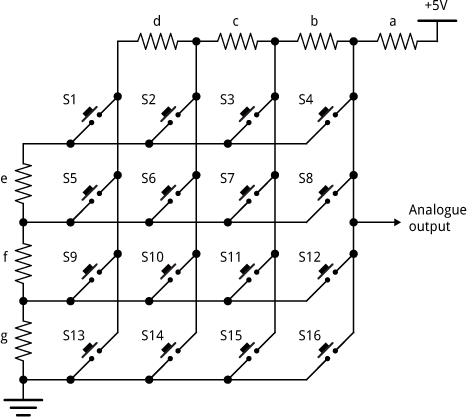
For an electronics project I was working on a while ago I wanted to see if it would be possible to find a set of resistors that would give a different voltage when each of the switches was pressed in the following circuit:

The aim was to decode a matrix keypad of 16 keys using just a single analogue input on a microprocessor [1].
An additional constraint was that the resistors should be from the standard E6 series of commonly available resistor values:
10 15 22 33 47 68, 100 150 220 330 470 680, ... etc
Also, the smallest gap between the resulting voltages should be as large as possible, to make decoding the switch presses as easy and reliable as possible, and to make the circuit tolerant of small inaccuracies in the resistor values.
Lisp program
Here's the Lisp program I used to calculate the best set of resistor values:
(defparameter e6
  '(10 15 22 33 47 68 100 150 220 330 470 680 1000 1500 2200 3300 4700 6800))

(defun matrix (e6)
  (let ((bestmin 0)
        values)
    (flet ((pushvalue (value)
             (push (truncate (* 1024 value)) values)))
      (dolist (a e6)
        (dolist (b e6)
          (dolist (c e6)
            (dolist (d e6)
              (dolist (e e6)
                (dolist (f e6)
                  (dolist (g e6)
                    (setq values nil)
                    (pushvalue (/ (+ b c d e f g) (+ a b c d e f g)))
                    (pushvalue (/ (+ b c e f g) (+ a b c e f g)))
                    (pushvalue (/ (+ b e f g) (+ a b e f g)))
                    (pushvalue (/ (+ e f g) (+ a e f g)))
                    ;;
                    (pushvalue (/ (+ b c d f g) (+ a b c d f g)))
                    (pushvalue (/ (+ b c f g) (+ a b c f g)))
                    (pushvalue (/ (+ b f g) (+ a b f g)))
                    (pushvalue (/ (+ f g) (+ a f g)))
                    ;;
                    (pushvalue (/ (+ b c d g) (+ a b c d g)))
                    (pushvalue (/ (+ b c g) (+ a b c g)))
                    (pushvalue (/ (+ b g) (+ a b g)))
                    (pushvalue (/ (+ g) (+ a g)))
                    ;;
                    (pushvalue (/ (+ b c d) (+ a b c d)))
                    (pushvalue (/ (+ b c) (+ a b c)))
                    (pushvalue (/ (+ b) (+ a b)))
                    (pushvalue 0)
                    ;;
                    (let* ((sorted (sort values #'<))
                           (diffs (map 'list #'- (cdr sorted) sorted))
                           (min (reduce #'min diffs)))
                      (when (> min bestmin) (setq bestmin min)
                        (format t "~a (~a ~a ~a ~a ~a ~a ~a)~%"
                                min a b c d e f g)))))))))))))
The dolist loops try every possible one of the e6 resistor values for the 7 variables, a to g, which represent the 7 resistors used in the circuit. The 16 calculations, such as:
(pushvalue (/ (+ b c d e f g) (+ a b c d e f g))))
then work out the 16 digital values, from the 10-bit analogue-to-digital converter, produced by pressing each of the push buttons. The last one is always 0; the one that connects the output to ground.
Then the last few statements find the minimum difference between any pair of the voltages; we want this to be as large as possible.
Finally if we’ve found a set of resistor values that’s better than the best so far I print it out (the format statement).
The result
Run the program with:
CL-USER > (matrix e6)
After leaving the program running for a couple of hours it produced this final result:
28 (150 15 15 150 47 47 22)
I was very pleased to find that not only was there a set of resistor values that give the required spread of voltages, but also that the best of these gives a generous gap of at least 28 between successive values from the 10-bit analogue-to-digital converter.
Because you can multiply all the resistor values by a fixed factor without affecting the result, I chose the values:
a = 15kΩ, b = 1.5kΩ, c = 1.5kΩ, d = 15kΩ, e = 4.7kΩ, f = 4.7kΩ, and g = 2.2kΩ.
Other ideas
I haven't investigated further, but it would be interesting to see how far one can extend this technique; perhaps it's possible to decode a matrix of 32 switches, or even more!
Update
14th August 2018: I recently used the same technique to design a circuit for a 20-key matrix; here are the details: Calculating resistors for a 20-switch matrix.
- ^ One Input Keypad Interface on Technoblogy.
blog comments powered by Disqus
